Generate Support Drawing
 Used to generat a support drawing
which involves exporting a group of support parts to an output drawing along
with descriptive data.
Used to generat a support drawing
which involves exporting a group of support parts to an output drawing along
with descriptive data.
Accessed from:
Drawing Production ribbon group
Supports can be placed in a group between pipe and steel object using the assembly option in which combinations of support parts are predefined. While placing assembly components are placed as single component but their detail information will get added to BOM Area.
To generate a support drawing from a placed assembly, select the General Support Drawing from the taskbar.
Select an assembly as shown below.
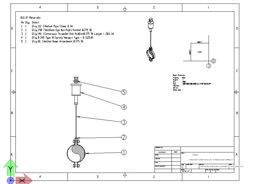
Left-click to accept the pick and the support drawing will be generated and opened in the application as shown: The support drawing is layed out as defined in the default OPSE_DrawingProduction.dgn which is included with the OpenPlant Modeler install. This drawing is stored in the following location: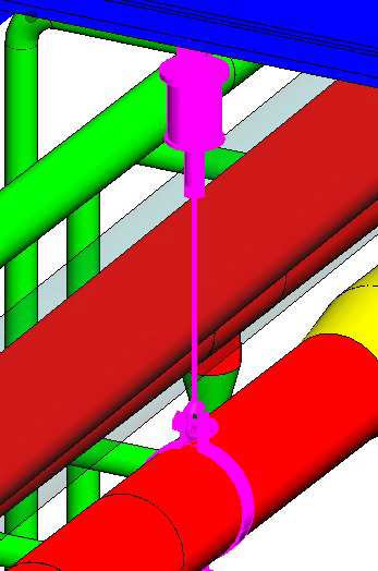
C:\ProgramData\Bentley\OPSE\WorkSpace\Projects\%Project%\Dataset\seed\
Each area in the support drawing displays a different information and the layout can be modified through the template file to appear any way you want.By default, the drawing contains the following information areas:
- Bill of Materials: This lists all of the components which make up the assembly/component. If the support component/assembly is attached to a Steel component, then the steel information is included as well.
- Default (Right) View: Shows a right view of the support/assembly labeled with numbered balloons which correspond with the Bill of Materials. If the support/assembly is connected to a Steel component, then a section of the steel is displayed as well.
- Isometric View: Shows an isometric view of the support/assembly.
- General Information (Properties): This area contains basic information about the support/assembly.

The Steel Cross Section option lets you add a cross section of the supporting steel structure to the support drawing after the drawing has been generated.
Refer to the Place Steel Cross-Section help for details on how this is placed.
Grid Lines
OpenPlant Modeler also supports the use of grid lines in models and provides the ability to include their use when generating a support drawing. If a grid system is in place in the current OpenPlant Modeler model, then, when a support drawing is generated, a graphic displays showing the assembly's position in relation to the nearest grid section. Distances from each grid line are provided as shown below:
Support Drawing Camera Position Parameter
The following project parameter defined in the Project Dashboard Settings > Project Parameters grid determines whether the defined support component views in the support drawing are view relative to the pipe supported, which is the default, or relative to the model.
CamPosReltoPipe =
where:
- CamPosReltoPipe = 1- The default value which displays the defined component views relative to the direction of the pipe supported.
- CamPosReltoPipe = 0 - The defined component views are relative to the actual model.
How it Works
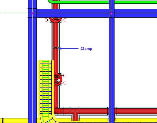
Using the example model below shown in a top view, there is a clamp placed on a pipe running in the Y direction:
When CamPosReltoPipe = 1 (default setting) in the Project Dashboard, when a support drawing is generated, a left view of this clamp relative to the pipe direction would display as shown:

When CamPosReltoPipe = 0, the left view of the clamp in relation to the model displays as follows:

Once the parameter has been modified and saved in the Project Dashboard, the OpenPlant Model will need to be refreshed and a new Support Drawing generated for the change to take place.
Support Drawings for Gang Supports
For the instances where supports are grouped (ganged) together, the user has the option when generating a support drawing to include all of the supports on one drawing, or generate separate drawings for each support component.
In the Project Dashboard > Project parameters grid, the following parameter defines this behavior:
SplitGangSupport
where,
- SplitGangSupport = 1 - This is the default value which will create split the ganged support into separate drawings, each detailing a different pipe attachment in the BOM.
- SplitGangSupport = 0 - With this option, all of the components of the ganged support will be detailed in a single support drawing.
Once the user has defined the parameter in the Project Dashboard, it must be saved in the Project Dashboard and the OPSE model must be refreshed before the settings are applied. Once this has been done, the changes are reflected the next time the support drawing is generated.
Example 1
The example displays how the support drawing is generated when the SplitGangSupport option is set to 0 and all of the support components are detailed on a single support drawing: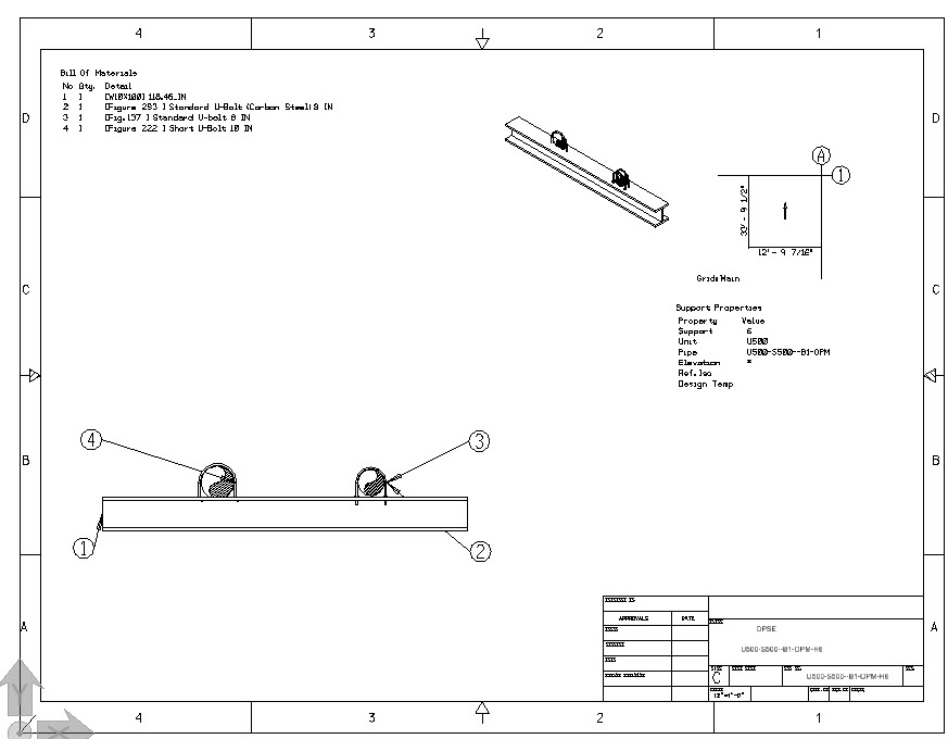
Example 2
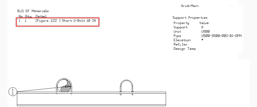
When the SplitGangSupport value is set to 1, the supports are split into separate support drawings. The first drawing will include the structural support as well as one of the pipe attachments as shown in the BOM:

The subsequent drawings will still display all of the components, but only one pipe attachment is detailed in the BOM:
Support Drawing BOM
The default Support Drawing template will include a BOM section which is customizable using the Expressions Manager as well as the Support Drawing parameters in the Project Dashboard.
See the Support Drawing Template Creation > Bill of Material section for additional details.